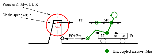
Figure 1-1, Force Diagram
TITLE: Modeling the Fixed-footboard Fanwheel Ergometer
SUBJECT: A comprehensive description of the computer model ERGMOM 2.00
AUTHOR:
William C. Atkinson, PE, USRA
343 South Ave., Weston, MA 02493-1948
watkinson@compuserve.com
KEYWORDS: ROWING, ERGOMETER, FANWHEEL, EXERCISER
ERGMOM:
This abstract describes the program ERGMOM 2.00, a comprehensive computer model of the dynamics of the fixed-footboard fanwheel rowing ergometer.
THE MODEL:
This model is a subset of the comprehensive ROWING model developed earlier but of course without oars, blades, coefficients of lift and drag, blade path geometry, block coefficients, footboard work, etc.
One significant feature of the two models taken together is that, for the first time, rowing and exercising can be compared in all significant respects.
ERGMOM makes no initial assumption as to the nature of the fanwheel velocity profile - such as defining it as portions of half-sine waves. The velocity profile produced by ERGMOM emerges as a natural consequence of the instantaneous forces involved and their action upon the fanwheel.
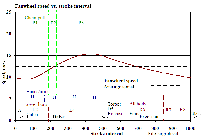
ERGMOM divides a single sweep stroke cycle into seventeen "regimes" (some overlapping, Figure 1-3) - twelve in its drive and eight in its free portions - in each of which forces of friction, propulsion, or momentum act. ERGMOM further divides each stroke into 1,000 time intervals. An incremental solution then proceeds, via iteration, for any specified free (sprocket disengaged) absolute time period. Using initial assumptions for wheel speed and for the ratio of the drive (sprocket engaged) to the free time periods ERGMOM adjusts this (drive/free) time period ratio until the calculated wheel revolutions during the drive portion of the stroke, as defined by the equation of motion, satisfies the corresponding revolutions, as required by the specified pull geometry.
ERGMOM models chain-pull and portions of the momentum exchange forces by means either of linear or parabolic force and velocity distributions.
Written in FORTRAN, ERGMOM runs under DOS 6.2.
o Fanwheel polar moment of inertia
o Wheel resistance factor (air) for various fan inlet damper settings
o Wheel friction torque
o Chain sprocket pitch diameter
o Chain return spring constant
o Slide, arm bend, reach and pull handle excursions (based on rower size)
o Weight and height of rower
o Added mass- effective mass of the bound fluid (contributing to the
inertial mass of the fanwheel)
o Peak fan handle chain-pull (two points) and pull force regime
accelerations. Force rise and fall may be specified as linear or parabolic.
o Free (sprocket disengaged) time period; the only gross timing parameter
under the control of the rower
o Momentum and momentum force regime acceleration timings for body mass
points (upper: torso, arms, head; and lower: hips, thighs; Figures 1-3, 2-4)
o Free acceleration of handle and upper body mass from the start to the
catch and the corresponding deceleration from the release to the finish
o Exponent of fanwheel angular velocity (w^x) where x may take any positive
value in the expression for the hydrodynamic resistance of the wheel -
commonly 2.0 but smaller values sometimes indicated in the literature
o Initial estimate of wheel speed and drive/free period ratio
Output values calculated by ERGMOM:
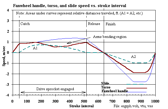
o Wheel speed (Figure 2-1; average, max/min (rad/sec))
o Stroke rating, 1/min; total, drive, and free period lengths
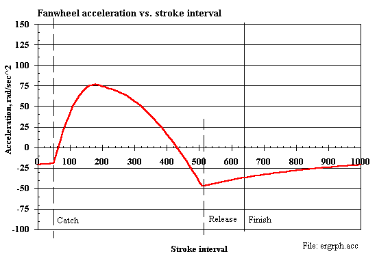
o Wheel acceleration (Figure 2-2)
o Wheel revolutions per stroke (rad)
o Work done on wheel; in momentum (internal, external); on return spring
(J/stroke)
o Frictional forces on the wheel
o Losses (wheel bearing friction work)
o Chain-pull impulse (N-sec)
o Unrecorded rower slide work (kgCal/hr)
o Unrecorded return spring work (J/stroke)
o Power expended by rower, internal, external, total, kw)
o Rower external efficiency, pull handle work/rower total work)
o System mechanical efficiency (fanwheel work /rower total work)
Output tables produced (ordinates vs. time and stroke interval; 1,000 instantaneous values per stroke cycle):
1. Cumulative time increments
2. Fanwheel speed
3. Fanwheel acceleration
4. Cumulative wheel revolutions
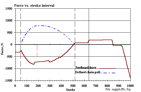
5. Chain-pull force
6. Wheel air friction resistance
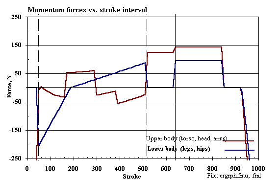
7. Upper body momentum force
8. Lower body momentum force
9. Footboard force
10. Upper body (torso) relative velocity
11. Cumulative net work done on wheel - must sum to zero
12. Slide relative velocity
13. Pull handle velocity
14. Incremental fanwheel power
Some program Figures follow. Except as noted here they need little explanation.

    Where:
     w = omega; instantaneous angular velocity of the fanwheel, rad/sec
     a = alpha; (dw/dt) = instantaneous angular acceleration of fanwheel,
         rad/sec^2
     r = pitch radius of pull chain sprocket, cm *
     k = radius of gyration of fanwheel (k of sprocket neglected), cm *
    Mf = mass of fanwheel on coast; add mass of sprocket on pull, kg *
    Mm = uncoupled (momentum) mass(es): Ml, lower body; Mu, upper body, kg *
    Mt = Total mass of system = Mf +Mm = undefined for ergometer
     I = Mfk^2 = mass moment of inertia of fanwheel, kg-m^2 *
    Pf = instantaneous chain-pull on the fanwheel sprocket, N *
    Ts = Pfr =instantaneous fanwheel sprocket torque, Kg-m
     K = fanwheel torque drag factor, (Kg-m)(sec^2/rad^2) [Tf=Kw^2]
    Tf = -K w^2 = instantaneous fanwheel air load torque, kg-m
     T = Tf +Ts, kg-m
       = Ia = I(dw/dt) = -Kw^2 +Pfr
    Equation of fanwheel motion:
              /w2
    t2 -t1 =I |  dw /(-Kw^2 +Pfr)
              /w1
    Vs = rw = instantaneous sprocket tangential velocity (chain and hands),
         M/s
    Vm = instantaneous velocity of the uncoupled mass(es), m/s
    Fm = uncoupled momentum force(s) on footboard = Mm(dVr/dt)
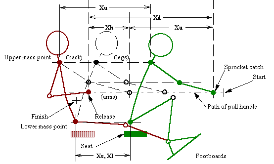
    Xr = Reach excursion (not applicable to ergometer- no oar catch angle)
    Xd = Total rower draw excursion (height related) *
    Xb = Hands/arms bend excursion *
    Xs = Slide excursion *
    Xu = Upper mass point excursion (torso, head)  = Xd -Xb
    Xl = Lower mass point excursion (hips, thighs) = Xs
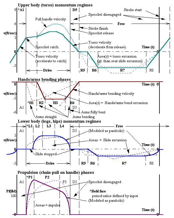
ATTACHED FIGURES:
Dynamic Ergometer Model (all plots show instantaneous values calculated by ERGMOM)
 Fanwheel Ergometer Model- Fixed footboard
  Man- 79 kg @ 30.0 1/min

 ERGOMETER: (ergmeter.dat)- Ver. 2.00 (At iteration   16)     11/16/ 1  8:41: 4
           Peak chain-pull-   778.4 & 778.4 N; Polar mom.-     0.1001 kg-m^2
      Stroke period length-     2.00 sec/cycle;    Rating-    30.00 strokes/min
    Drive/run period ratio-     0.888;  Sprocket diameter-     0.02835 m
              Drive period-     0.941 sec;    Free period-     1.059 sec
    Calculated turns: DrvC-    77.271 rad; Geomtric: DrvA-    77.419 (iterated)
 WHEEL SPEED:      Initial-    61.92 rad/sec;       Final-    61.99  (iterated)
             Minimum ( 61)-    59.68;       Maximum (429)-    96.38; Amp.= 36.7
                   Average-    77.68 rad/sec;  Rower wgt.-    79.4 kg
    Resistance setting, Ka-     0.000400 (damper); Implse-   512.82 N-sec
 WORK:   Fanwheel friction-  -544.91 J/stroke;     Expt.w-     2.000
      Momentum lower, ext.-     0.00; Momntm. lower, int.-    60.08
       Return spring, ext.-    43.50; Momntm. upper, int.-   140.13
            External total-    43.50;      Internal total-   200.21
   Fanwheel net (residual)-     0.46;   Est. bearing loss-    -1.05
            Fanwheel shaft-   545.50;  Slide (unrecorded)-    86.07 kgCal/hr
          Pull-handle work-   589.00;   Pull-handle power-     0.2946 kw
          Total rower work-   789.21;         Rower power-     0.3947 kw
 EFF:  Fanwheel mechanical-     0.999;  System mechanical-     0.690
2. In the ERGMOM 2.00 computer model output (Table 2-1, above):
a. The return spring work (about ten percent) is unrecorded as work done by
the rower at the ergometer display. (ERGMOM includes the "negative" spring
work done on the free return which, depending on interpretation, might
reasonably be excluded from work done by the rower.)
b. The internal work lost in the rower's own body is large (86 kgCal/hr) and
is unrecorded at the ergometer display.
c. The rower's body air resistance loss (admittedly small) is unrecorded - and
is neglected by the ERGMOM model as well.