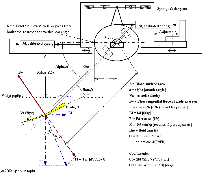
Figure 1, A Schematic Lift-Drag Test Rig

Because this blade is not free to rotate with respect to the shaft it would probably not be possible to measure induced drag or to determine moment coefficients, Cm. But, for the same reason, these two variables may not be important arbiters of blade performance in rowing.
A large fetch of turbulence-free water is required. Relative motion between the water and the blade must cover a control range from about one to five m/s whether it is the water or the rig that moves. Measurements will probably be easier with a moving rig (towing tank) unless a variable speed source of moving water can be found ready made. There may be towing tank facilities available greatly to simplify parts of the work (USNavy, David Taylor Model Basin, WDC; Stevens Institute, Hoboken, NJ; etc.). Coefficients should be determined over a range of blade area, form, attack angle, attack velocity, and Reynolds' number.
If it could be arranged to measure the torque and drag forces simultaneously while driving the pivot to sweep the blade at typical rowing speeds against the water flow then the results might be more accurate (modeling a rotating blade).