Cast a vote here if you think it should move up in the Top-100 ranking:

You will be transferred to the Top-100 site, but may then return here by going "BACK"

New data on the lift and drag characteristics of oar blades have recently (2006) been put forward by N. Caplan , N. and T.N. Gardner .
Specifically they address the lift and drag characteristics of a blade
modeled as a flat plate, a Dreissigacker "Big Blade", and a traditional
"Macon" blade in a relatively narrow and shallow experimental channel. The
data differ from the Hoerner data (see below) in that:
o There is no significant stall at any attack angle.
o The new characteristics can be reasonably approximated by simple sine
functions of the attack angle, a. See
Rowing Biomechanics News
o The differences in lift coefficient are negligible; and the differences in
the drag coefficient small.
In regard to sine(a) modeling the lift coefficient is Cl = Al *sin(2a) where Al is the half-amplitude of the measured Cl vs. alpha function and the drag coefficient is Cd = Ad *(sin(a))^2 where Ad is the amplitude of the drag function.
For the flat plate: Al = 1.3, Ad = 2.0
For the Big Blade: Al = 1.25, Ad = 2.07
For the Macon blade: Al = 1.24, Ad = 1.90
The new data have been run in ROWING for a single scull, heavy man, at about 28.1 1/min for equal total rower power (525.3 w/rower) and equal blade surface area (715.4 cm^2). Since drag rules the waves the Big Blade (Vavg.= 4.40 m/s) bested the Macon (Vavg.= 4.38 m/s)- by 1.4 sec/2000m. Efficiencies were as follows: Big Blade- blade 0.80, system 0.60; Macon- blade 0.79, system 0.59.
The average shell velocity difference from the flat-plate data is about two percent making it not worthwhile to recalculate any of the relative ROWING results in this paper.
The difference in peak drag coefficient found by the authors for the flat (2.0) and curved blades (2.1) indicates that curvature is a probably a good thing.
Some caveats are in order. In the case of the Macon it is not clear whether Caplan tested blades of equal submerged surface area which I think could lead to result irregularities in light of the small test channel used in relation to the blade sizes.
Historical data show that, at a ninety degree angle of attack, drag coefficient increases steadily with aspect ratio (narrowness) leading one to expect the skinnier Macon to have shown higher drag values than the fatter Big Blade for equal surface area.
Until 2009 ROWING has used the only data available- that for totally immersed flat plates at various angles of attack. New data is now available for actual oar blades (see above), but we have not undertaken the considerable work required to rerun the illustrative cases below. The new coefficient values change the absolute force values to some extent but have little effect on the diagrammatic results.
The data are as follows:
   C Oar blade lift and drag coefficients
     Hydrofoil: Flat plate, fully immersed, b/c=0.2, after Hoerner
   C Attack angle
   C ---- ----- ----- ----- ----- ----- ----- ----- ----- ----- ----- -----
      0.0   1.0   2.0   3.0   5.0   7.0  10.0  15.0  20.0  25.0  30.0  33.0
     35.0  37.0  39.0  41.0  42.5  42.5  45.0  50.0  60.0  70.0  80.0  90.0
   C Lift coefficient
   C ----- ----- ----- ----- ----- ----- ----- ----- ----- ----- ----- -----
     0.0   .0300  .065  .105  .185  .265 0.39  0.61  0.83  1.04  1.23  1.33
     1.36  1.38  1.37  1.35  1.30  0.73  0.71  0.67  0.56  0.40  0.21  0.0
   C Drag coefficient
   C ----- ----- ----- ----- ----- ----- ----- ----- ----- ----- ----- -----
     0.0   .0005  .001  .005  .015 0.03  0.07  0.17  0.31  0.49  0.71  0.84
     0.93  1.01  1.08  1.15  1.20  0.66  0.71  0.80  0.96  1.09  1.17  1.20
   C Stall angle  Stall point
   C -----------  -----------
            42.5           18
To the extent that a plate or an airfoil may not be considered "fully
immersed" these flat plate values- or any "airfoil" values for that matter-
are undoubtedly inaccurate, but it is hard to imagine how they could be better
(contributing more to boat propulsion) than those for the fully immersed
condition. Hoerner's flat plate ratio (b/c, length/width) above is for plate shapes where length(b) is seen as always perpendicular to the flow and width(c) at some angle to it. To the extent that a plate or an airfoil may have a large or infinite aspect ratio (long and narrow like a slat) the Hoerner data cannot apply. Hoerner's aspect ratios vary from about 0.2 for a Big Blade, 0.3 for a Macon blade, and 1.0 for a square. In this context a blade like a hammerhead shark would have an aspect ratio greater than one.
However, as the angle of attack approaches ninety degrees the concept of aspect ratio, in relation to its orientation to the flow, gradually changes in relation to lift- which disappears- and to drag- which is maximised. In this regime aspect ratio is always defined as greater than one, as in wing terminology. Square plates have Cd about 1.2 and extreme toothpicks of about 2.0.
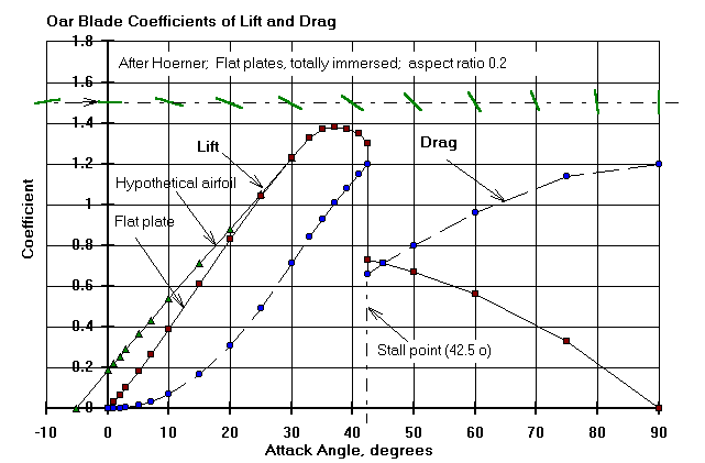
Also plotted here is the lift coefficient of a hypothetical blade with the zero attack angle characteristic of an airfoil (the stall points for most airfoils are around fifteen degrees). Its lift coefficient at zero angle of attack is NOT zero. This leads us to wonder whether positive lift at small attack angles (at and near the catch) is a benefit to rowers. At smalll angles of attack would it be a good thing to have an "airfoil" blade in preference to a simple flat plate?
Let those who laugh at flat plate data send me something better. Because the foil operates for half of the drive at an attack angle less than fifteen degrees (Fig. 4-7a, below) lift at small angles may be important. ROWING shows that the lift force is constant for an extended period at about 20kgf for the hypothetical foil and 10kgf for the flat plate.
Somewhere near an attack angle of forty degrees (oarshaft bow angle of seventy degrees) a flat plate blade stalls, but stall seems to have little effect on the lift and drag forces (Fig. 4-7, below). I would be interested to hear whether rowers can feel this subtle discontinuity in the otherwise smoothness of their strokes.
Near the catch and the finish an efficient blade should manifest high lift and, near the ninety degree point, high drag characteristics both aimed at maximising the propulsive force vector, Fs. I must continually remind readers that the magnitude of the lift and drag forces are functions solely of the rower's instantaneous effort at the oar handle- having nothing whatever to do with blade design.
The aim in rowing is to transfer as much as possible of the rower's effort to the oarlock with the minimum of blade slip. Slip is minimized by maximizing the hydrodynamic vector resultant of lift and drag. Near the catch and release high lift is useful, and near the ninety-degree point high drag is essential.
Unfortunately, where it may be most wanted, lift has a limited effect owing first to the fact that the shell-longitudinal components of the forces are small at small oarshaft bow angles and second to the fact that the rower's effort at the beginning and end of the stroke is small. It takes time for his effort to build to its maximum near mid-stroke so that at the stroke ends his effort is small and, correspondingly, the lift is small.
Figures 4-7 and 4-7a show how ROWING plots the calculated lift and drag forces, attack angles, and velocities for a single scull, heavy man.
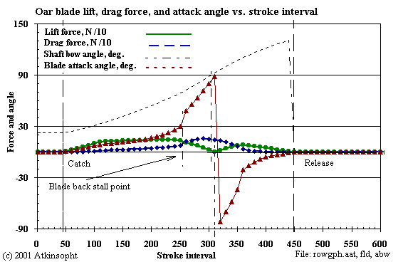
1. Flat Plate at 507 W/rower at 26.7 1/min:
The result shown here is calculated from the coefficients for a flat blade.
One can see exactly how the motion of the blade is related to the lift and the
drag. For an accurate ROWING result the coefficients of lift and drag should
be known for the entire 180 degree range of the blade's attack angle.
In the early stages of the motion the lift force, which must at all times balance the rower's effort, is small- less than 10 kgf.
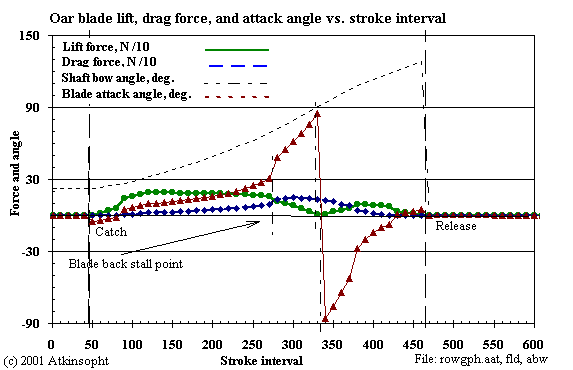
2. Airfoil Shape at 508 W/rower:
The result shown here is calculated for an "airfoil" blade at the same
rower total power as for the flat blade. The expectation was that this
would lead to a significant improvement in shell speed.
This blade has positive lift at zero attack angle and zero lift at an attack angle of -5.2 degrees. Thus, the initial attack angles are negative (as calculated) and increase to zero and above only as the rower's handle effort builds with time. Correspondingly the lift force begins and ends at zero.
In the early stages of the motion the lift force, which again must at all times balance the rower's effort, is higher (20 kgf) than that for the flat plate (10 kgf).
The increase in blade efficiency (0.77 to 0.83) permits a higher rating in order to produce equivalent rower total power. But the speed increase is disappointing because of the increased internal work (209J vs. 178J) required during the shortened free recovery time. The slip is greater for the airfoil shape because in this case the blade is in the water longer (longer drive time) even though the blade efficiency is improved (0.83 vs. 0.77).
3. Airfoil Shape at 26.7 1/min:
The increase in blade efficiency (0.77 to 0.83) requires less rower total
power. But there is no speed increase because of the untapped rower power.
Summary:
The improvement in the blade lift characteristic seems to have produced no
substantial improvement in shell speed.
   Blade lift characteristic comparison:
         Clift @  Shell  Ratg. Drive   Rtrn. Rtrn.  Abs.  Rower  Systm. Blade
        0 attack  speed        /rtn.   time  work   slip  power   eff.   eff.
           angle    m/s   1/m  ratio    sec     J      m      W
        ========  =====  ====  =====  =====  ====  =====  =====  =====  =====
1. Flat    0.0     4.58  26.7  0.685   1.33   178   0.62    507   0.68   0.77
2. Foil    0.065   4.61  27.7  0.727   1.26   209   0.64    508   0.69   0.83
3. Foil    0.065   4.56  26.7  0.679   1.34   189   0.65    481   0.71   0.83
In all cases above the sculler's peak force (580N) and force profiles are the same.
Positive lift at zero attack angle shifts the zero-slip path of the blade center bow-ward in the same way as does negative cant angle. In fact, the zero lift attack angle may be simply added to the blade cant angle and the resulting tractrix calculated directly for comparison with the actual blade center locus as modified by slip. A massless, free, and unloaded blade seeks the path of zero lift until acted upon by an external force - such as that of the rower.
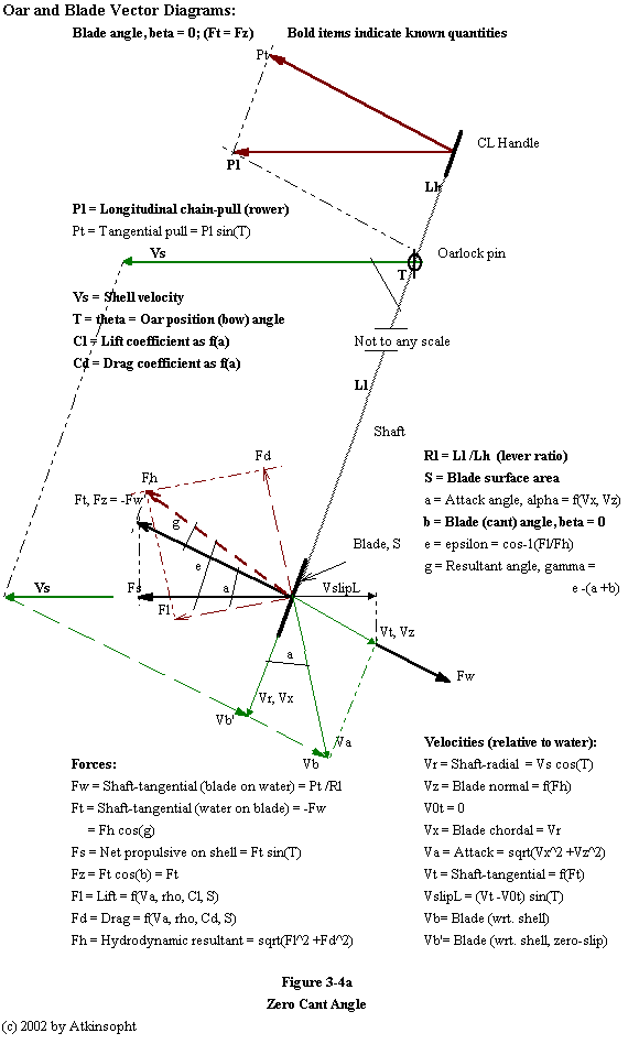
The shaft tangential reaction on the blade by the water Ft (= -Fw) is always (almost) in static equilibrium with the tangential force (Pt) on the handle (the oar having small mass and acceleration) - the oar is a simple beam with a mid support and a load at each end. Ft is uniquely determined by Pt (and not by blade characteristics). In addition, Fh cos(g) (= Ft), the blade normal component of the hydrodynamic resultant of the lift and drag forces, must balance Fw - as shown in Figure 3-4a above. This equality is the key to the understanding and the determination of slip.
The blade's shaft radial velocity (Vr) is a function only of the instantaneous shell speed (Vs) and shaft bow angle (Theta); Vr = Vs cos(T). The blade's attack velocity (Va) is its velocity relative to the water: being the vector sum of the blade's shaft radial (Vr) and its shaft tangential (Vt) velocities - its slip velocity - which is a function of its attack angle, its lift and drag coefficients, its surface area, and the water density (and to some degree upon Reynolds' number). If the rower exerts no effort on the handle Vr is always Vs cos(T) and the attack angle is always zero degrees for a flat blade (and negative for an "airfoil" blade) throughout the entire stroke.
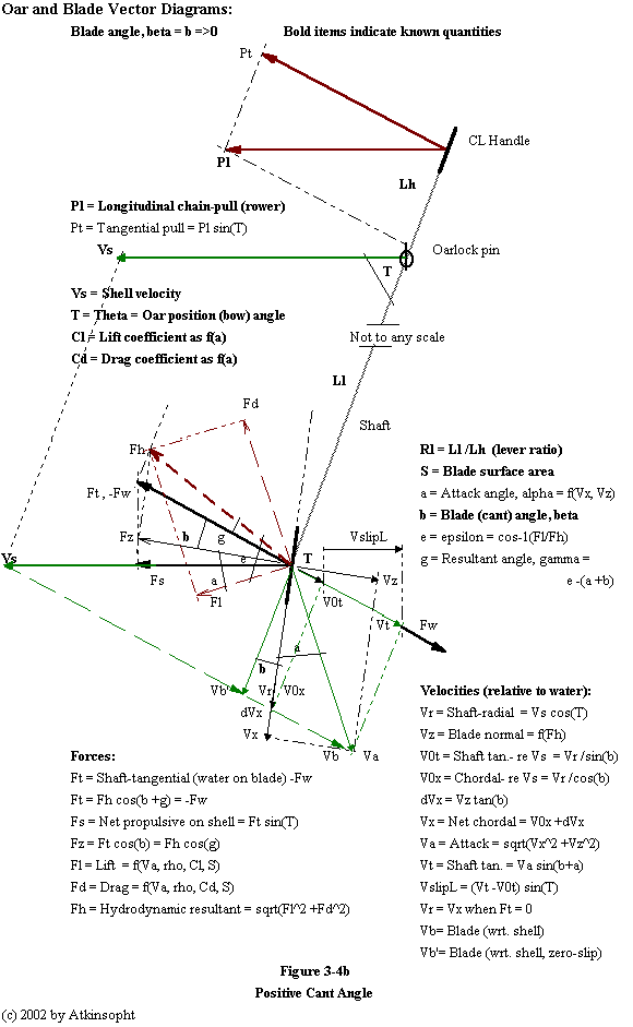
Figure 3-4b above is the same as Figure 3-4a except that the blade cant angle, beta, is non-zero. Although this diagram is therefore more complex the vector relationships are similar.
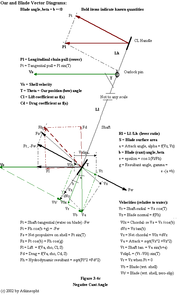
Same as Figure 3-4b above except bata is negative.
"Nature" iterates instantly and automatically but from the calculational point of view the lift-drag-slip relation in ROWING must be determined by trial and error convergence mathematics.
At first, at any instant of the stroke, only the blade reaction force at the water is known. In order to calculate the instantaneous blade slip and the lift and drag forces from oarblade characteristics the attack angle and velocity must also be known. However, these attack parameters cannot be found without prior knowledge of the slip. ROWING at first assumes an arbitrary drag coefficient from which an initial slip velocity is found from the force, blade surface, and water density. From this slip velocity an attack angle and attack velocity are found and from them, in turn, new slip and attack velocities. The new and "old" slip velocities are compared, an appropriate adjustment is made, and the values recalculated until the error residual is insignificant- usually in about five iterations in each of the approximately five-hundred stroke drive instants considered. 2,500 slip iterations per stroke- let's hear it for gigaflops.
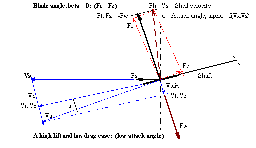
Figure 3-5a a case (near the catch) at high lift and low drag. ROWING will now handle bladeforms whose lift coefficients are positive at zero angle of attack.
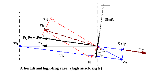
Figure 3-5b a case (near mid stroke) at low lift and high drag.
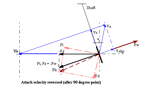
Figure 3-5c a case late in the stroke after the ninety-degree shaft point has been passed.
The blade normal component, Fz, of the hydrodynamic resultant, Fh, always balances the tangential force, Ft, produced by the rower's effort on the oarhandle. If the rower stops pulling Fz vanishes.
Fh will always rise (through slipping) to meet the value of Ft no matter what the lift and drag characteristics of the blade (whether Smoothie or floor mop). This is analogous to the balance between Fh and weight in an airplane wing. Therefore, if the required Fh - a function of the coefficients, water density, surface area, and slip velocity squared - can be produced by a sophisticated blade design (of best coefficients) the slip velocity, Vz, will be correspondingly small, i.e, more efficient; producing lower slip for a given applied force. This is how lift and drag affect oarblades.
Note that if an oar blade does not slip the blade itself "absorbs" zero power, thus no useful power is ever "applied to the blade" as some seem to believe. The available rower's power is applied solely to the oarlock and footboard. The blade absorbs (wastes) power only to the extent that it slips. This is easy to visualize by replacing the water with a fixed post or a prepared curved track. The blade against the post has zero slip and, because the post does not move, no work is lost because the distance the earth is moved backward as a result is truly infinitesimal.
And now for those wanting something "entirely different" try soccer balls for oar blades.
Increasing the zero attack angle lift coefficient - through the use of an airfoil form - increases lift in the "pinch" portions of the sweep. However, the ROWING model shows that increased lift in this early part of the stroke seems to have little effect on the overall reduction of slip.
Increasing the drag coefficient increases blade efficiency by increasing drag near the ninety-degree point of the sweep.
More or less rectangular blade shapes with aspect ratios (length/width) between two and three have ninety-degree attack angle drag coefficiients on the order of 1.18. For square blade forms Cd=1.16, and for circular disks Cd=1.12. Thus, square and circular blade forms are probably not as good as rectangular ones of comparable surface area.
Skinny (high aspect ratio) shapes have even higher drag coefficients but aspect ratios above about six become unwieldy. An infinite aspect ratio has a Cd=2.0. Thus a Macon blade, of the same surface area, might be preferable to a Big Blade. Who knows until we experiment? The traditional blades of fishermen and seamen have always been long and thin, perhaps a design honed by cultural evolutionary experience over tens of thousands of years. It was easier too, before the advent of lamination technology, to fashion a narrow blade from a given stick of wood.
In ROWING increasing the relative magnitude of the lift coefficient by fifteen percent (if this is, in fact, physically possible in relation to a fixed drag coefficient) leads to very small changes in average shell speed and blade efficiency- on the order of only 1 percent- at equal total rower power. In fact the speed actually decreases slightly with lift coefficient. This confirms my belief that lift plays an unimportant role as a useful oar blade attribute.
And so, as shown by the ROWING model, we reach the conclusion that there may turn out to be little to be gained by improving the lift or the stall characteristics of blades in order to reduce their absolute longitudinal slip. A NACA 5403 airfoil, with a profile very much like a scull spoon, stalls at an attack angle of about three degrees, smaller than any but those in the earliest part of the stroke.
Skin friction and profile drag should, be minimized. High values tend to check the shell near the catch and the finish. Roughnesses introduced at the tip of the blade (to enhance turbulence) should probably be tested for their effect on such profile drag.
Design the spoon for the cleanest possible entry at the catch. Since, at the instant of entry under zero rower effort, the attack angle is always that which produces zero lift it would seem that this angle should be carefully determined and the entry edge form made to agree with it. For this refinement it will be necessary to determine the lift coefficients at small angles of attack. In this regard, blades whose lift at zero attack angle is zero, should probably be flat.
In any event, now that we have some computational ability to evaluate blades
of differing hydrodynamic characteristic, it seems certain that the time has
come for those with the interest and the means to take a serious look into the
improvement of blades.
Here is a schematic set-up for the measurement of lift and drag in a channel with some notes on other approaches.
With proper dimensional scaling blade forms could be studied in the windtunnel- but without, of course, learning anything about the effects of partial immersion.
What seems to count is high drag at the ninety-degree point of the sweep - which should also be the peak force point. The ROWING model seems to show that the blade surface area should be as large as the rower can effectively manage.
As shown in the ROWING indications for blade cant angle consideration should probably be given to blades with negative angle.
And, lastly, we must remind ourselves again that boats do NOT move forward because (necessarily a mass of) water is moved backward. Boats move forward because the mass of the earth is moved backward; and it matters not whether the oarblade is connected to the earth through the agency of yielding water or of unyielding post. An ideal shell would move NO water backward in this process of moving the earth. The perfectly efficient way of thus moving the earth is through the agency of a frictionless roller in a prepared and curving slot, i.e., the tractrix defining the zero-slip blade locus.